Gas Governor Meter Pulse Transmitter Modules
Use these pin-outs alongside our gas metering commissioning and instrumentation and telemetry services to keep meters, pulse modules, and downstream data capture aligned.
Dresser Meters: RJ11 Pulse Transmitter
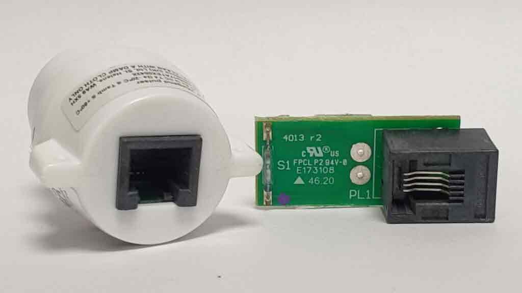
Dresser meters are widely used and typically include a pulse transmitter mounted to the side of the mechanical index. The index is driven by impellers that rotate with the gas flow. A magnet within the index passes a reed switch inside the transmitter to generate a pulse, which we can condition and feed into metering data acquisition systems.
- Reed switch connects to pins 2 and 3 of the RJ11 plug (the two centre contacts).
- Pulses represent volume counts as configured by the meter and transmitter.
RJ11 Pulse Transmitter
Middle two contacts carry the pulse.
Dresser: 4-Pin Circular EGG Socket
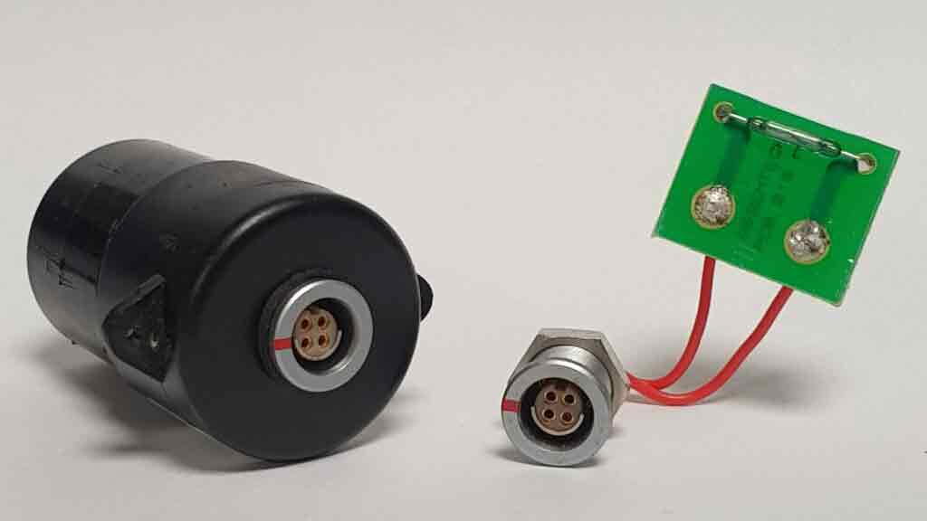
Some Dresser transmitters use a 4-pin circular "EGG" connector. In this arrangement, the reed switch connects to pins 3 and 4. With the red mark at 12 o'clock, both contact pins are on the left-hand side.
4-Pin Circular Connector
The reed switch on pins 3 and 4.
Elster Diaphragm Meters: Pulse and Tamper
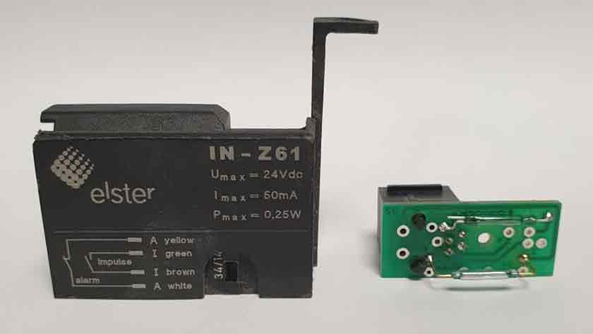
Elster diaphragm meters have their own pulse transmitter with two outputs: the main volume pulse and a tamper alarm. Both use the same RJ11 plug as Dresser meters, and Elster modules include a printed diagram indicating pin assignments.
- Two outputs: volume pulse and tamper.
- Confirm pulse type, scaling, and connector pinout on site.
Elster Pulse Transmitter
The contact pins are the two middle contacts of the RJ11 plug.
Turbine Meters: 6-Pin Circular Connectors
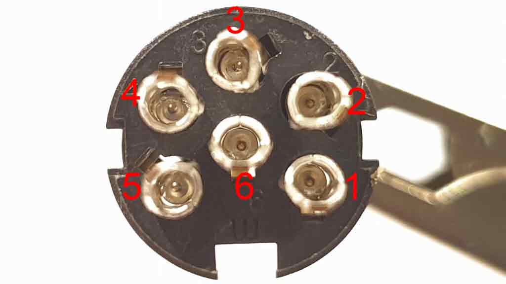
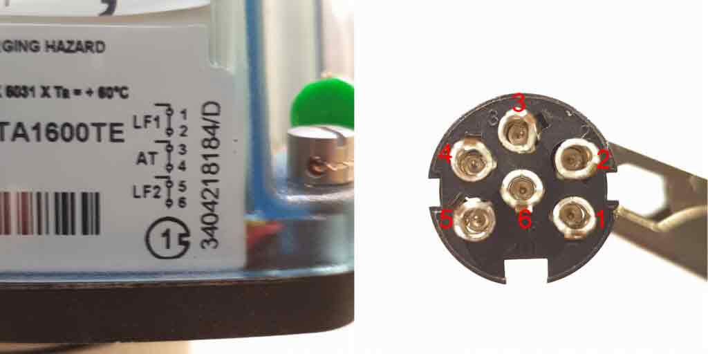
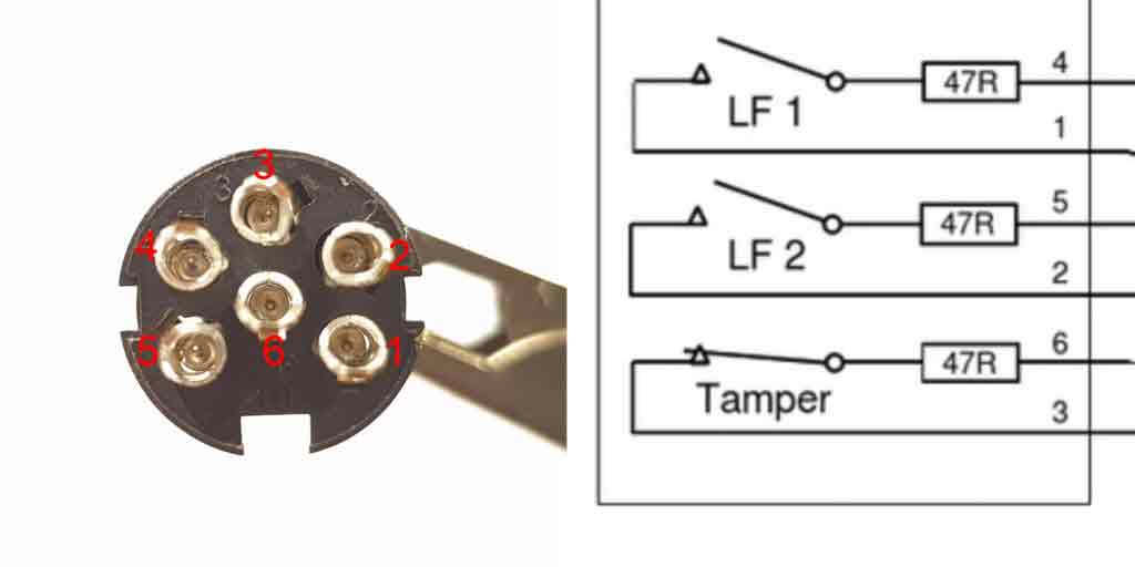
Most turbine meters for natural gas use a 6-pin circular connector for pulse acquisition. FMG and Itron are the most common brands. Although they share the same plug type, their pulse modules have different wiring. Both manufacturers include wiring diagrams on the mechanical index.
- Itron: pins 1-2 and 5-6 for pulses; pins 3-4 for tamper.
- FMG: pairs 1-4 and 2-5 for pulses; pins 3-6 for tamper.
6-Pin Circular Connector
Always confirm wiring from the printed diagram on the index.
Itron LF Wiring
Typical low-frequency (LF) wiring on Itron turbine meter modules.
- Pulses on pins 1-2 and 5-6
- Tamper on pins 3-4
Itron LF Wiring Diagram
Pulse 1-2, 5-6; tamper 3-4.
FMG LF Wiring
Typical low-frequency (LF) wiring on FMG turbine meter modules.
- Pulses on pairs 1-4 and 2-5
- Tamper on pins 3-6
FMG LF Wiring Diagram
Pulse 1-4, 2-5; tamper 3-6.
